building a tonearm
Posted: Wed Apr 10, 2019 1:31 pm
This follows on from an arm build I did about 18 months ago, not the first arm I've built, but a collection of ideas I've been kicking about for a while....
Jump forward to now, and having had something of a lean period in terms of work, I decided to revisit the unipivot. I had some other ideas for it over the last couple of months, and having had the md65 lathe for a good while I decided to use it for this project. Or series of ideas rather than project.
So having got hold of some 25mm round steel bar, and an electric sharpener that I got for drill bits and wood chisels and modified to allow me to sharpen the metal lathe tools, I thought I'd build the ideas I had into something. To see if it would work.
It's taken about a week on and off to make all the parts, probably about 8 hours work in total. I didn't want to buy any bits in, I wanted to make them myself because I'm stubborn. Only thing left to make is the bias weight. All turned from steel apart from the headshell which is made from 3mm aluminium to keep weight down.
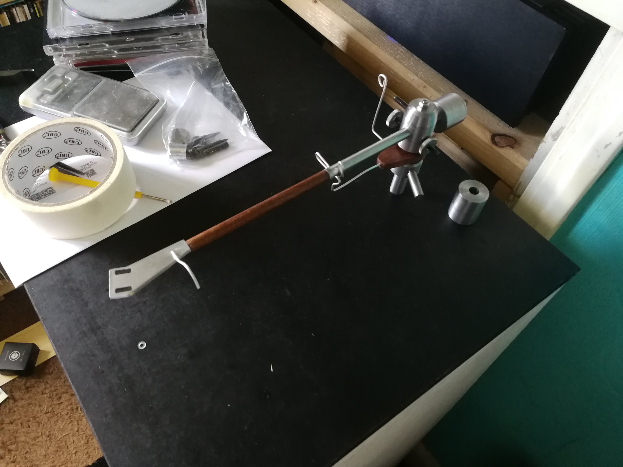
A collection of parts
 Cx unipivot mk iv by anthony cresswell, on Flickr
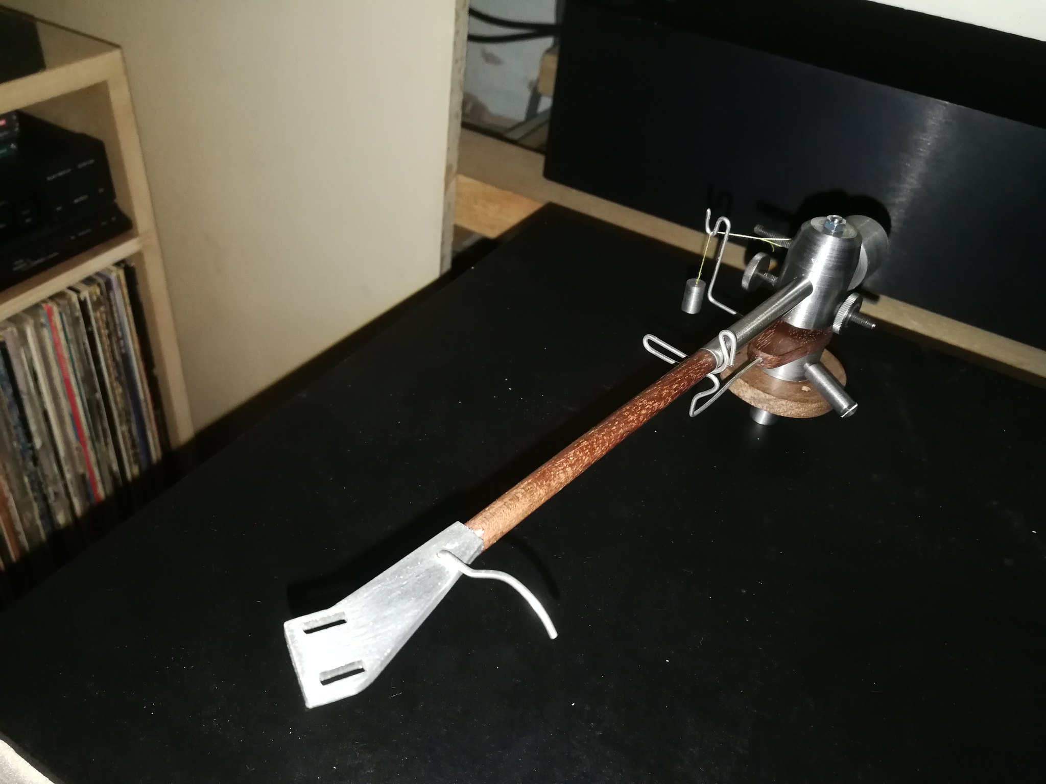
Built up into the arm
 Cx unipivot mk iv by anthony cresswell, on Flickr
The part not fitted is a heavier counterweight. The fitted on is 75g, the other is 100g
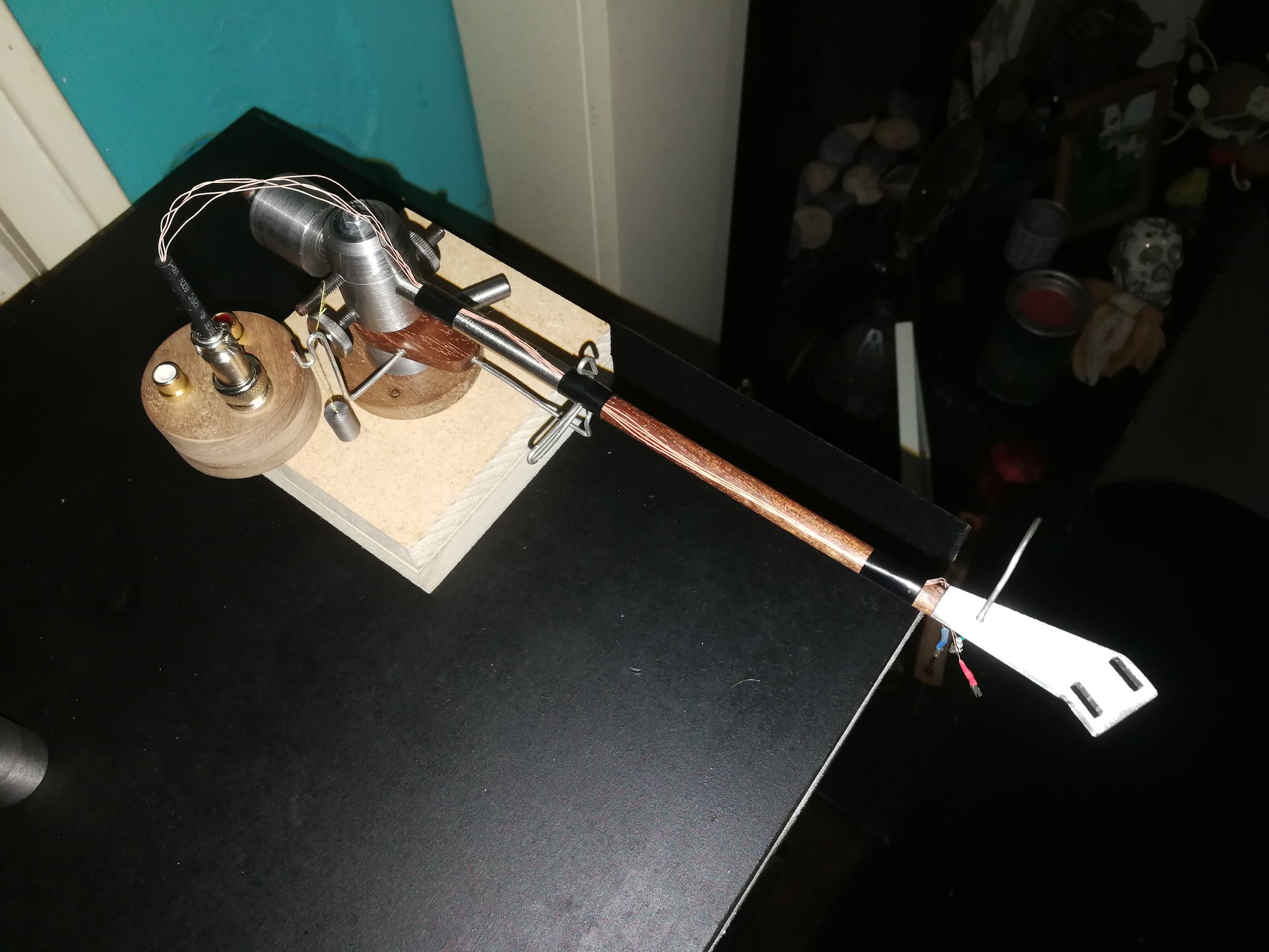
a top view
 Cx unipivot mk iv by anthony cresswell, on Flickr
The cylinder stuck out at an angle is the setscrew for locking the arm height. I borrowed this idea from the audiomods arm as it is alot easier to get hold of rather than fiddling with an allen key or screwdriver to lock the arm in place.
and a side view
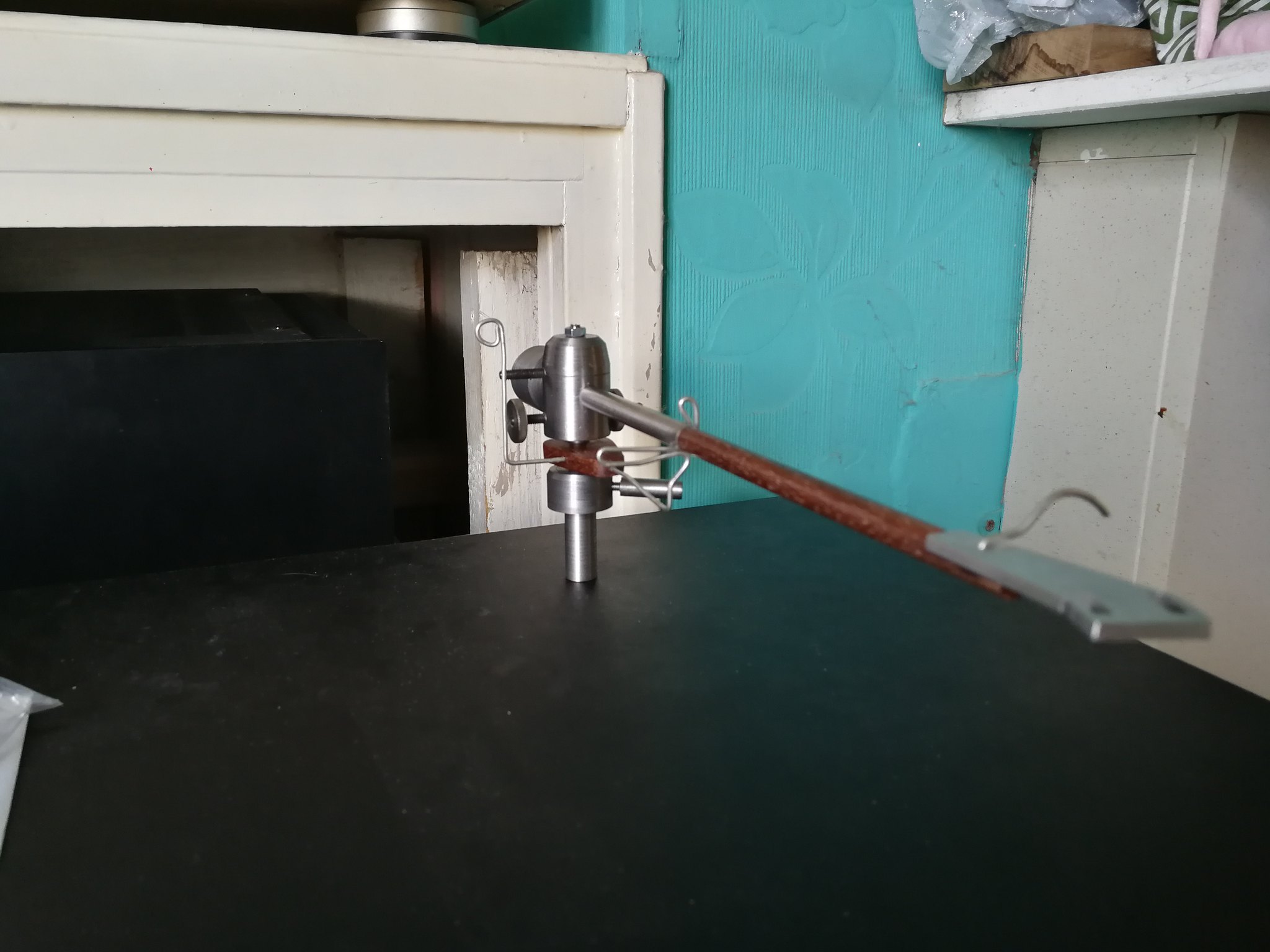 Cx unipivot mk iv by anthony cresswell, on Flickr
This is an inverted bearing, the spike is fitted into the arm wand pointing down, an sits in a cup in the top of the arm pillar. this can be filled with silicone fluid to damp the pivot, same as the original. I also kept the wire arm rest and bias weight 'thing' of the original as it was nice and simple
original
 Lenco with u/p mods by anthony cresswell, on Flickr
This one however does not have the bearing pivot point at the same height as the stylus, as this led to unpredictable azimuth on stuff that was quite warped, so the pivot is set just a little higher than the top of the arm tube to get all the weight lower than the pivot. There were ways around this characteristic, by moving the weight around and reducing weight above the pivot, thats for the next prototype.
The problematic bias location on the original has been moved so that it follows the Hadcock pattern of being on the left rather than out of the back of the housing as on the original. this caused issued with setting the cart tracking weight and was too fiddly.
the counterweight is not dropped and is on axis with the main arm tube instead, as I wanted to separate the azimuth and the tracking weight adjustment. The azimuth is adjusted by the two weights on the left and right of the bearing housing and is much less fiddly than skewing the main counterweight off to the left or right, and gives plenty of clearance at the back which was a problem with the original, plus, the majority of the weight of the assembly is lower than the pivot on this version so its not necessary from a stability point of view.
The arm tube is a composite of 8mm stainless tube at the back and Makore hardwood at the front. The idea was gotten from an origin live arm that uses aluminium and carbon fibre sections to alter the resonance of the arm, and I liked the wood and steel idea. the wooden section was turned on the wood lathe into a larger blank, which was turned down on the metal lathe so that a 30mm section could be glued into the steel, then it was all turned and trued on the metal lathe into a complete wand.
To get the headshell on, I bodged myself a rudimentary milling machine out of the pillar drill and an old lathe cross slide. Stuck a twin flute router bit in the drill chuck and used the cross slide to mill the 3mm deep section out of the end of the wand. Worked perfectly. No good whatsoever for metal, but fine for this particular job. It was spot on for drilling out the holes to make the bolt slots in the headshell though, it meant that the chain of holes were positioned perfectly.
One thing I did forget to do was to drill out the inside of the wooden section of the arm tube to take the wiring, so I'll have to tape the wiring on the outside to test it. There is always something.......
It took abit longer than strictly necessary to make the parts, but in my defence, I needed to get a feel for the lathe and how the steel turned having not really made anything in steel on it other than some really small things where dimension weren't important. Also used a shit-ton of wd40 as cutting fluid especially when boring and tapping as the proper stuff I ordered still hasn't turned up... Martin at the local engineering place suggested it in the interim as he didn't have any I could buy, he just had a huge great drum of the stuff that they use in the workshop. Worked nicely though.
I also got an aerosol air duster to blow the chips away at his suggestion, they use an air line, but also have some of these knocking about for if the air line is in use on something else. A quid from the local pound shop, it was really useful. Nothing worse than the chips building up on the tool and sticking to the cutting fluid so you cant really see the cutting edge of the tool, the steel cut fine dry on the exterior cuts but abit of fluid was needed to get a nice fine finishing cut. The interior boring needed loads of fluid though, you can feel it when it needs abit more.
Haven't got the hang of thread cutting with it yet though so I just used taps this time. Need more practice....
Jump forward to now, and having had something of a lean period in terms of work, I decided to revisit the unipivot. I had some other ideas for it over the last couple of months, and having had the md65 lathe for a good while I decided to use it for this project. Or series of ideas rather than project.
So having got hold of some 25mm round steel bar, and an electric sharpener that I got for drill bits and wood chisels and modified to allow me to sharpen the metal lathe tools, I thought I'd build the ideas I had into something. To see if it would work.
It's taken about a week on and off to make all the parts, probably about 8 hours work in total. I didn't want to buy any bits in, I wanted to make them myself because I'm stubborn. Only thing left to make is the bias weight. All turned from steel apart from the headshell which is made from 3mm aluminium to keep weight down.
A collection of parts
Cx unipivot mk iv by anthony cresswell, on FlickrBuilt up into the arm
Cx unipivot mk iv by anthony cresswell, on FlickrThe part not fitted is a heavier counterweight. The fitted on is 75g, the other is 100g
a top view
Cx unipivot mk iv by anthony cresswell, on FlickrThe cylinder stuck out at an angle is the setscrew for locking the arm height. I borrowed this idea from the audiomods arm as it is alot easier to get hold of rather than fiddling with an allen key or screwdriver to lock the arm in place.
and a side view
Cx unipivot mk iv by anthony cresswell, on FlickrThis is an inverted bearing, the spike is fitted into the arm wand pointing down, an sits in a cup in the top of the arm pillar. this can be filled with silicone fluid to damp the pivot, same as the original. I also kept the wire arm rest and bias weight 'thing' of the original as it was nice and simple
original
Lenco with u/p mods by anthony cresswell, on FlickrThis one however does not have the bearing pivot point at the same height as the stylus, as this led to unpredictable azimuth on stuff that was quite warped, so the pivot is set just a little higher than the top of the arm tube to get all the weight lower than the pivot. There were ways around this characteristic, by moving the weight around and reducing weight above the pivot, thats for the next prototype.
The problematic bias location on the original has been moved so that it follows the Hadcock pattern of being on the left rather than out of the back of the housing as on the original. this caused issued with setting the cart tracking weight and was too fiddly.
the counterweight is not dropped and is on axis with the main arm tube instead, as I wanted to separate the azimuth and the tracking weight adjustment. The azimuth is adjusted by the two weights on the left and right of the bearing housing and is much less fiddly than skewing the main counterweight off to the left or right, and gives plenty of clearance at the back which was a problem with the original, plus, the majority of the weight of the assembly is lower than the pivot on this version so its not necessary from a stability point of view.
The arm tube is a composite of 8mm stainless tube at the back and Makore hardwood at the front. The idea was gotten from an origin live arm that uses aluminium and carbon fibre sections to alter the resonance of the arm, and I liked the wood and steel idea. the wooden section was turned on the wood lathe into a larger blank, which was turned down on the metal lathe so that a 30mm section could be glued into the steel, then it was all turned and trued on the metal lathe into a complete wand.
To get the headshell on, I bodged myself a rudimentary milling machine out of the pillar drill and an old lathe cross slide. Stuck a twin flute router bit in the drill chuck and used the cross slide to mill the 3mm deep section out of the end of the wand. Worked perfectly. No good whatsoever for metal, but fine for this particular job. It was spot on for drilling out the holes to make the bolt slots in the headshell though, it meant that the chain of holes were positioned perfectly.
One thing I did forget to do was to drill out the inside of the wooden section of the arm tube to take the wiring, so I'll have to tape the wiring on the outside to test it. There is always something.......
It took abit longer than strictly necessary to make the parts, but in my defence, I needed to get a feel for the lathe and how the steel turned having not really made anything in steel on it other than some really small things where dimension weren't important. Also used a shit-ton of wd40 as cutting fluid especially when boring and tapping as the proper stuff I ordered still hasn't turned up... Martin at the local engineering place suggested it in the interim as he didn't have any I could buy, he just had a huge great drum of the stuff that they use in the workshop. Worked nicely though.
I also got an aerosol air duster to blow the chips away at his suggestion, they use an air line, but also have some of these knocking about for if the air line is in use on something else. A quid from the local pound shop, it was really useful. Nothing worse than the chips building up on the tool and sticking to the cutting fluid so you cant really see the cutting edge of the tool, the steel cut fine dry on the exterior cuts but abit of fluid was needed to get a nice fine finishing cut. The interior boring needed loads of fluid though, you can feel it when it needs abit more.
Haven't got the hang of thread cutting with it yet though so I just used taps this time. Need more practice....